Connection Syntax (Advanced)
Users can override the automatic connection signatures by specifying repeat counts; by changing the dimensions or by specifying which object elements connect to which. To this end Blueprint provides a Connection Dialog that allows users to specify their own loops, switches and connections using the full connection Syntax
The advanced connection syntax extends the basic syntax to include the user specified loops and selections
Adv Signature:
{Basic Signature} | {Loop} | {Switch}
Loop:
{Dim} [ . {Loop}]
Switch:
< {Switch index} > { {Switch Signature} [{Switch Signature}] }
Switch Index:
{Connectee Index} | {Connector Index}
Switch Signature:
{Case Selector}{Adv Signature}
Case Selector:
< [{Max Value}] [ , {Min Value}] >
Min Value:
Max Value:
{Value}
Eg. K<#0>{<2,1>[0]<4,3>L[1]} with 'Repeat count' R
for each element of connector object
for 1..K
switch #0
case 1..2:
for repeat count R
ConnectTo( 0 )
case 3..4:
for 1..L
for repeat count R
ConnectTo( 1 )
Irregular Connections
In some cases an even more advanced connection logic is required that cannot be defined by simple loops and switches. To this end Blueprint allows irregular connections to be defined via user defined macro functions.
In the following examples the an array of consumer objects only requires connections to a sub set of the provider objects (both same dimension). The first is a 1-d example, the second a 2-d example.
Example 1
The 1-d Collector is required to make a sub set of connections to the semaphore, depending on its element number.
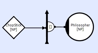
Each collector element 'n' connects to a pair of Counting Semaphores 'n' and 'n+1'. However, if 'n' is odd it must connect to element 'n' then 'n+1', if even it must connect in the opposite order 'n+1' then 'n'. When 'n+1' is greater then the number of elements, it must wrap around to element 0.
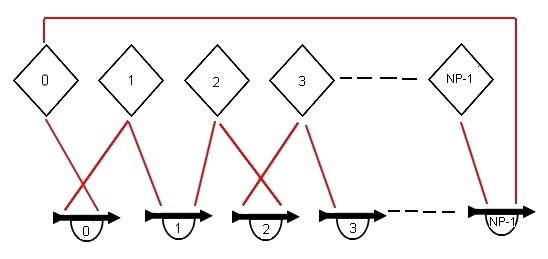
If NP is known then this connection 'could' be configured using the switch mechanism, but this could be cumbersome and prone to errors, especially if NP was to be changed. To make this connection using macros we need to generate two macro functions 'First()', 'Second()', and make connections using these.
These functions can be defined in the ProjectHeader.hpp file. Each function generates a single element number.
#define NP 7
#define First( X ) ( ((X)%2) ? (X) : (((X)+1)%NP) ) // if odd connect to X else X+1 - wrap X+1 to 0 if required
#define Second( X ) ( ((X)%2) ? (((X)+1)%NP) : (X) ) // if odd connect to X+1 else X - wrap X+1 to 0 if required
In this example the arguments to the macros are simply the loop variable, but this not a restriction. We could have passed other parameters into the macro
Eg.
#define Next( N, X, Y ) ( ((N)==1) ? ( ((X)%2) ? (X) : ( ((X)+1) % (Y) ) ) : ( ((X)%2) ? ( ((X)+1) % (Y) ) : (X) ) )
ConnectTo( Next( 1, #0, NP ) )
ConnectTo( Next( 2, #0+1, NP/2 )
Example 2
In this 2-d grid example each collector needs to make a sub set of connections the the data store depending on the its element number.
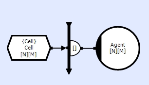
Each collector n,m connects to its 8 neighbours and itself (in a specific order).
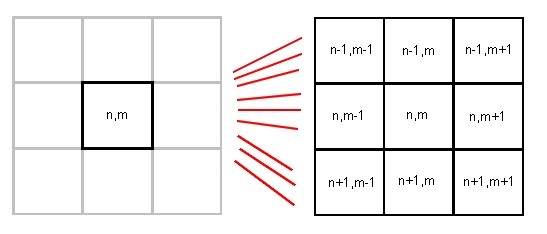
The connections also need to wrap around at the each edges/corners of the grid.
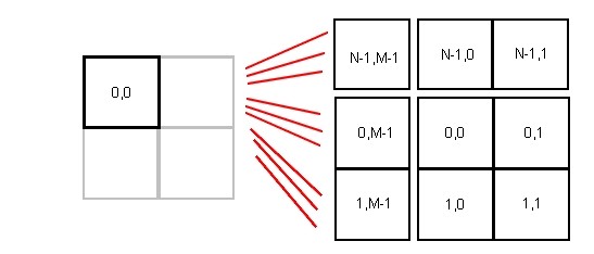
To configure this connection using switches and cases would be extremely arduous and only possible if N and M where known (and small).
We can make this connection using macros. To do this we need to generate macro functions with the following formats (since it must generate 2 values and used to initialise a array of constants)
#define G( X ) something // NB. G and H could be the same
#define H( Y ) something
#define F( X, Y ) G( X ), H( Y ) // NB. no outer brackets around the G,H functions
generated code
const Uns elem[2] = { F( e1, e0 ) };
which after macro substitution is equivalent to
const Uns elem[2] = { G( e1 ), H( e0 ) };
Thus for this example we would define the macros (in ProjectHeader.hpp)
#define N 10
#define M 10
#define Wrap( Xi, X ) ( ((X)+(Xi)) % (X) )
#define Wrap2( Ni, Mi ) Wrap( (Ni), (N) ), Wrap( (Mi), (M) )
Using the connection dialog the to create these nine connections would have generated a connection dimension of [9]. In this example, this is is not particularly useful, so using the connection dialog we can overwrite the dimension to [3][3]. However, there are a number of restrictions that must be observed with redimensioning connections.
Connection Dimensions
If the user overrides the connection dimension, this new dimension is validated against the calculated dimension. Warnings are generated if there is a mismatch that is plausible (highlights the fact that it has been changed), whilst errors are generated if there is an implausible or dangerous mismatch.
Eg.
Calculated Dimension User Specified Dimension Condition Comments
[9] [3][3] Warning Splitting a dimension is allowable
[3][3] [9] Warning Combining a dimension is allowable
[4][3] [2][6] Error Splitting one dimension and combining with another is not recommended
[2][9][4] [9][8] Error Combining (or splitting) non-adjacent dimensions is not recommended
[10] [3][3] Error Dimension mismatch
[N] [2] Error Dimension mismatch
[3][4][2] [4][3][2] Error Dimension reordering is not recommended
[N][2] [N*2] Error Can only combine (or split) numeric dimensions
There are a number of conditions where it is not possible to calculate a connection dimension from a signature. This usually occurs when there are different connection structures within switch cases, or flat loops (as opposed to nested loops) with different loop sizes or internal structures.
Eg
switch
case 1
connect to element 1;
case 2
connect to elements 1 and 2;
...
case N
for X in 1..N
connect to element X
In this instance there are different dimensions for each case (1, 2, N).
When a dimension cannot be calculated, a dimension of [*] will be used by the Translator to generate an access function with 1 argument (plus any repeat count argument) and thus it is up to the user to decode the connection structure to get to the actual connection element number.
NB: The access functions generated from [*] connections will not check do any dimension bounds checking.
If the user overrides a [*] dimension it is assumed the user knows best and thus the user specified dimension will be used by the translator.